1. To understand the diffraction, diffraction grating and how diffraction grating works with the help of basic diffraction grating equations and experimental studies.
2. To measure the wavelength of the light source with the help of diffraction grating.
Interference refers to the interaction of two or more wave trains of light having the same frequency and having a phase difference which remains constant with time (coherent sources), so that they may combine with the result that the energy is not distributed uniformly in space but is a maximum at certain points and a minimum (perhaps zero) at others.
(8.1)Diffraction phenomenon is described as the apparent bending of waves around small obstacles and the spreading out of waves past small openings. Diffraction patterns are marked by a rapid decrease in intensity with increasing distance from the center of the pattern.
A diffraction grating is made by making many parallel scratches on the surface of a flat piece of transparent material. It is possible to put a large number of scratches per centimeter on the material, e.g., the grating to be used has 6000 lines/cm on it. The scratches are opaque but the areas between the scratches can transmit light. Thus, a diffraction grating becomes a multitude of parallel slit sources when light falls upon it.
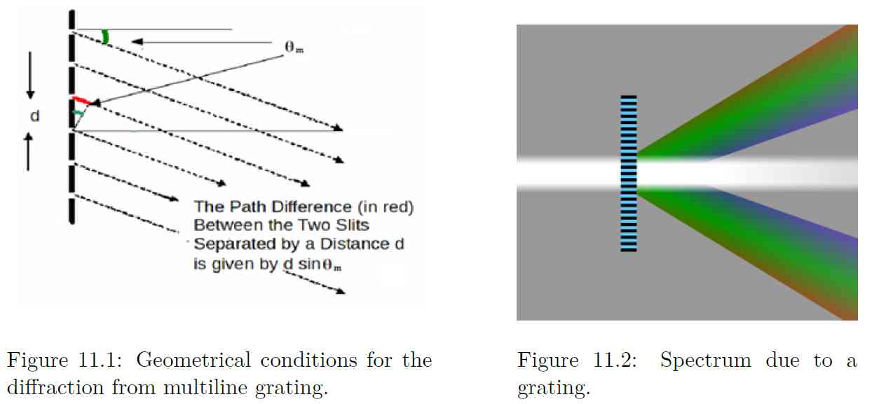
When parallel bundle of rays falls on the grating, these rays and their associated wave fronts form an orthogonal set so the wave fronts are perpendicular to the rays and parallel to the grating (as shown in Fig. 11.1). According to Huygens’ Principle, every point on a wave front acts like a new source, each transparent slit becomes a new source so cylindrical wave fronts spread out from each. These wave fronts interfere either constructively or destructively depending on how the peaks and valleys of the waves are related.
Whenever the difference in path length between the light passing through different slits is an integral number of wavelengths of the incident light, the light from each of these slits will be in phase, and then it will form an image at the specified location. Mathematically, the relation is simple
(11.1)
Eq. (11.1) is known as grating equation. The light that corresponds to direct transmission

(or specular reflection in the case of a reflection grating) is called the zero order, and is denoted m = 0. The other maxima occur at angles which are represented by non-zero integers m. Note that m can be positive or negative, resulting in diffracted orders on both side of the zero order beam.
Diffraction gratings are often used in monochromators, spectrometers, lasers, wavelength division multiplexing devices, optical pulse compressing devices, and many other optical instruments.
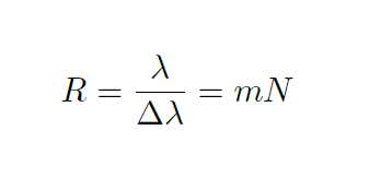
This equation then leads to the following expression for the resolving power of the diffraction grating
(11.2)R = λ/δλ = mN
Here λ is the average of wavelength, δλ is the difference between wavelengths, m is the order and N is the total number of slits on the grating. Thus, the distance between maxima depends on the distance between slits and the resolution,the relative sharpness of the maxima, depends on the total number of slits. (Often a grating is characterized by the number of slits per unit length. From this information one can, of course, deduce the distance between the slits..